Description
Specification:
CNC guard:
1. PWM spindle and direction pin
2. 4-axis support (X, Y, Z, A- can copy X, Y, Z or use the custom firmware to perform the completed 4th axis using pins D12 and D13)
3. 2 x end stop for each axis (total of 6)
4. Coolant activation
5. Use a detachable A4988 or DRV8825 compatible stepper drive
6. Compact design
7. Stepper motor can be connected or soldered in place using a 4-pin molex connector
8. Please note that this is an unassembled kit that requires basic soldering techniques.
A4988 stepper motor driver:
1. Low RDS (on) output
2. Automatic current decay mode detection / selection
3. Mix with slow current decay mode
4. Synchronous rectification for low power consumption
5. Internal UVLO
6. Cross current protection
7. 3.3 and 5 V compatible logic power supplies
8. Thermal shutdown circuit
9. Ground fault protection
10. Load short circuit protection
11. Five optional step modes: full, 1 / 2, 1 / 4, 1 / 8 and 1/16
UNO R3 Arduino Board of Directors:
1. MCU: ATmega328
2. USB interface: ATmega16U2
3. Working voltage: 5V
4. Digital I / O pins: 14 (including 6 with PWM function)
5. Analog input pin: 6
6. I-I / O pin output current: up to 40mA
7. 3.3V output current: up to 150mA
8. Flash: 32kB (including 0.5kB used by the bootloader)
9. Static RAM (SRAM): 2kB
10. EEPROM: 1kB
11. Clock speed: 16MHz
Package List:
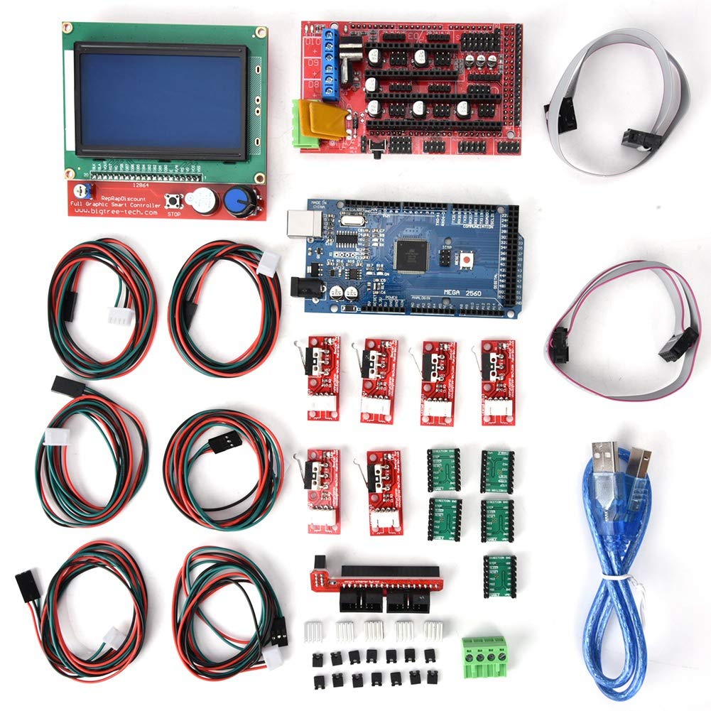
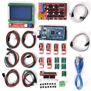
1*RAMPS 1.4
1*Mega 2560 R3
5*A4988 stepper motor drivers (with heat sink)
1*LCD 12864 graphic intelligent display controller
5*Limit Switches
1*USB Cable
CNC guard:
1. PWM spindle and direction pin
2. 4-axis support (X, Y, Z, A- can copy X, Y, Z or use the custom firmware to perform the completed 4th axis using pins D12 and D13)
3. 2 x end stop for each axis (total of 6)
4. Coolant activation
5. Use a detachable A4988 or DRV8825 compatible stepper drive
6. Compact design
7. Stepper motor can be connected or soldered in place using a 4-pin molex connector
8. Please note that this is an unassembled kit that requires basic soldering techniques.
A4988 stepper motor driver:
1. Low RDS (on) output
2. Automatic current decay mode detection / selection
3. Mix with slow current decay mode
4. Synchronous rectification for low power consumption
5. Internal UVLO
6. Cross current protection
7. 3.3 and 5 V compatible logic power supplies
8. Thermal shutdown circuit
9. Ground fault protection
10. Load short circuit protection
11. Five optional step modes: full, 1 / 2, 1 / 4, 1 / 8 and 1/16
UNO R3 Arduino Board of Directors:
1. MCU: ATmega328
2. USB interface: ATmega16U2
3. Working voltage: 5V
4. Digital I / O pins: 14 (including 6 with PWM function)
5. Analog input pin: 6
6. I-I / O pin output current: up to 40mA
7. 3.3V output current: up to 150mA
8. Flash: 32kB (including 0.5kB used by the bootloader)
9. Static RAM (SRAM): 2kB
10. EEPROM: 1kB
11. Clock speed: 16MHz
Package List:
1*RAMPS 1.4
1*Mega 2560 R3
5*A4988 stepper motor drivers (with heat sink)
1*LCD 12864 graphic intelligent display controller
5*Limit Switches
1*USB Cable
ASHATA 3D Printer Accessory Motherboard Kit for Mega 2560 R3 + A488 with Heat Sink USB Cable Kit
Current Price
$49.99
Average
$46.03
Min Price
$42.59
Max Price
$49.99
Price dynamics
8%
Description
Specification:
CNC guard:
1. PWM spindle and direction pin
2. 4-axis support (X, Y, Z, A- can copy X, Y, Z or use the custom firmware to perform the completed 4th axis using pins D12 and D13)
3. 2 x end stop for each axis (total of 6)
4. Coolant activation
5. Use a detachable A4988 or DRV8825 compatible stepper drive
6. Compact design
7. Stepper motor can be connected or soldered in place using a 4-pin molex connector
8. Please note that this is an unassembled kit that requires basic soldering techniques.
A4988 stepper motor driver:
1. Low RDS (on) output
2. Automatic current decay mode detection / selection
3. Mix with slow current decay mode
4. Synchronous rectification for low power consumption
5. Internal UVLO
6. Cross current protection
7. 3.3 and 5 V compatible logic power supplies
8. Thermal shutdown circuit
9. Ground fault protection
10. Load short circuit protection
11. Five optional step modes: full, 1 / 2, 1 / 4, 1 / 8 and 1/16
UNO R3 Arduino Board of Directors:
1. MCU: ATmega328
2. USB interface: ATmega16U2
3. Working voltage: 5V
4. Digital I / O pins: 14 (including 6 with PWM function)
5. Analog input pin: 6
6. I-I / O pin output current: up to 40mA
7. 3.3V output current: up to 150mA
8. Flash: 32kB (including 0.5kB used by the bootloader)
9. Static RAM (SRAM): 2kB
10. EEPROM: 1kB
11. Clock speed: 16MHz
Package List:
1*RAMPS 1.4
1*Mega 2560 R3
5*A4988 stepper motor drivers (with heat sink)
1*LCD 12864 graphic intelligent display controller
5*Limit Switches
1*USB Cable
CNC guard:
1. PWM spindle and direction pin
2. 4-axis support (X, Y, Z, A- can copy X, Y, Z or use the custom firmware to perform the completed 4th axis using pins D12 and D13)
3. 2 x end stop for each axis (total of 6)
4. Coolant activation
5. Use a detachable A4988 or DRV8825 compatible stepper drive
6. Compact design
7. Stepper motor can be connected or soldered in place using a 4-pin molex connector
8. Please note that this is an unassembled kit that requires basic soldering techniques.
A4988 stepper motor driver:
1. Low RDS (on) output
2. Automatic current decay mode detection / selection
3. Mix with slow current decay mode
4. Synchronous rectification for low power consumption
5. Internal UVLO
6. Cross current protection
7. 3.3 and 5 V compatible logic power supplies
8. Thermal shutdown circuit
9. Ground fault protection
10. Load short circuit protection
11. Five optional step modes: full, 1 / 2, 1 / 4, 1 / 8 and 1/16
UNO R3 Arduino Board of Directors:
1. MCU: ATmega328
2. USB interface: ATmega16U2
3. Working voltage: 5V
4. Digital I / O pins: 14 (including 6 with PWM function)
5. Analog input pin: 6
6. I-I / O pin output current: up to 40mA
7. 3.3V output current: up to 150mA
8. Flash: 32kB (including 0.5kB used by the bootloader)
9. Static RAM (SRAM): 2kB
10. EEPROM: 1kB
11. Clock speed: 16MHz
Package List:
1*RAMPS 1.4
1*Mega 2560 R3
5*A4988 stepper motor drivers (with heat sink)
1*LCD 12864 graphic intelligent display controller
5*Limit Switches
1*USB Cable
Price will be lower
in next 2 weeks
in next 2 weeks
According to the data, price will be lower in next two weeks, so not waste your money and track better price!
Product review & video
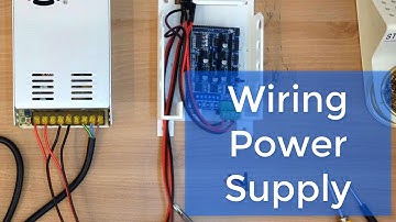
Cut off the receptacle or female connector of the power cord. Cut out the cable jacket with a nipper and a stationery knife. Pay attention to the color of each wire. If you use an automatic wire stripper, it will be more convenient. About 1.5cm will be okay for the length of the stripped wire. Cut the red wire(+ pole) at the point of about 20cm from the end. Strip about 1.5cm of insulation. Insert 5mm-width heat shrink tubes BEFORE you start soldering. Do the same soldering job for
the other wire. Shrink the insulation tubes with
a heat gun. Check the correct position of the switch. For easier operation, separate the power terminal of the RAMPS board. Make sure of the polarity of each pin. Connect the RED wire to +V and the Black wire to -V.


Similar products