Description
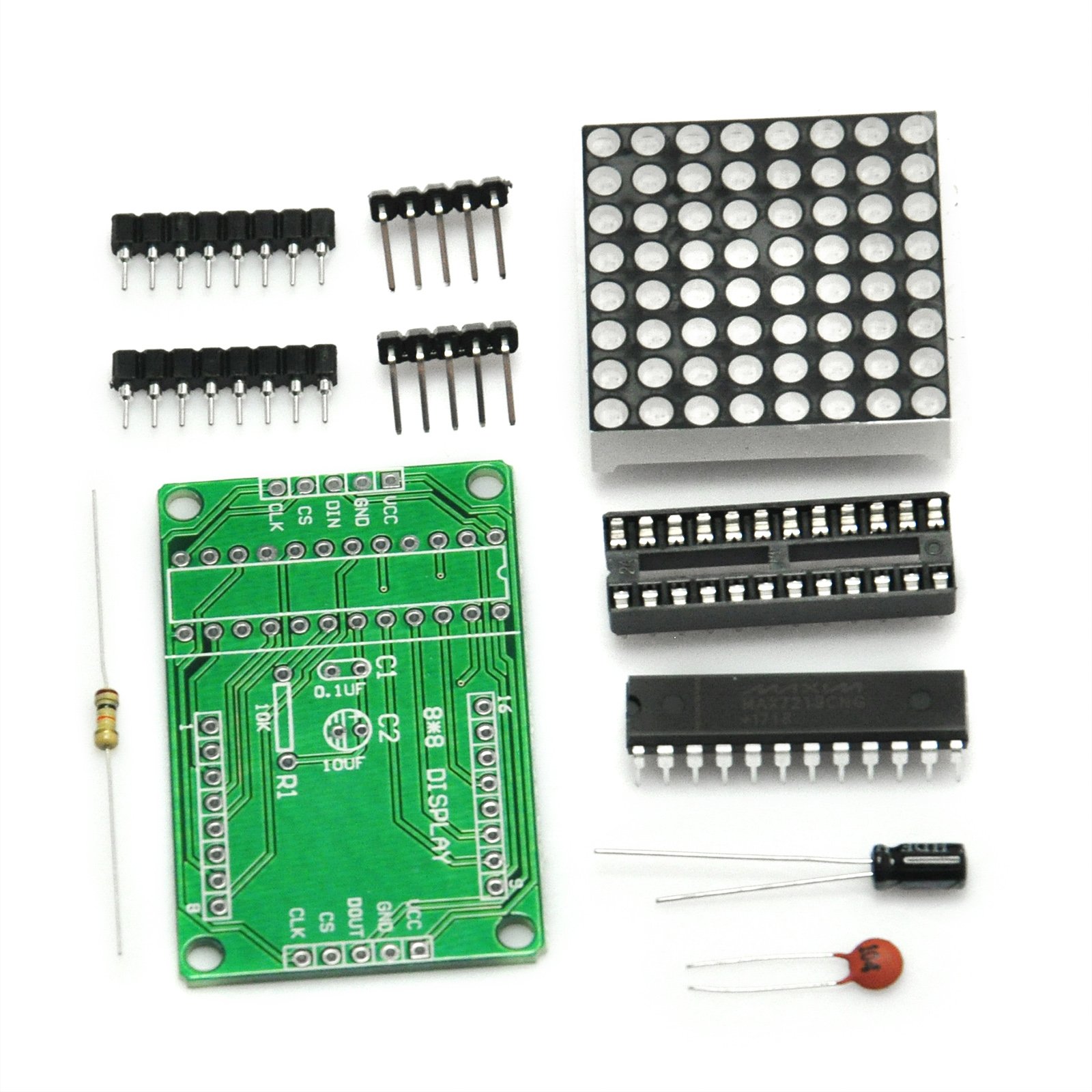
The MAX7219 is an integrated serial input / output common-cathode display driver, it is connected to a microprocessor with 8digit 7segment digital LED display can also be connected to the bar graph display or 64 separate LED. On B BCD encoder including an on chip, multi channel scanning loop word drive, but also an 8 x 8 static RAM is used to store each data. Only one external register is used to set the current of each LED segment.
Specifications:
The module left as an input port to the output port on the right.
The control of a single module, simply input port to the CPU.
Module Operating voltage: 5V.
Module size: 5 cm long X 3.2 cm wide X 1.5 cm high.
With 4 fixed screw holes for easy installation.
Multiple modules cascade input termination CPU, 2 output termination module, a module of the input of the input terminal, the output terminal of the first two modules of the first three modules, and so on ...
For Example:
51 MCU
VCC → 5V
GND → GND
DIN → P22
CS → P21
CLK → P20
Note:
VCC and GND is not reversed, it would burn the chip!
When the 51 microcontroller P0 port control, must be connected to the pull-up resistor, it is recommended that the resistance of 4.7K--10K.
Please lattice into the hole first seat, and then inserted into the round hole Block PCB board welding. Lattice word side facing the surface order from left to right pin 123456. PCB board 1 foot square pad.
Electrolytic capacitors long-legged as positive, negative short legs; ceramic capacitor without the positive and negative points.
Package content: 2 x MAX7219 Dot Matrix Module
Specifications:
The module left as an input port to the output port on the right.
The control of a single module, simply input port to the CPU.
Module Operating voltage: 5V.
Module size: 5 cm long X 3.2 cm wide X 1.5 cm high.
With 4 fixed screw holes for easy installation.
Multiple modules cascade input termination CPU, 2 output termination module, a module of the input of the input terminal, the output terminal of the first two modules of the first three modules, and so on ...
For Example:
51 MCU
VCC → 5V
GND → GND
DIN → P22
CS → P21
CLK → P20
Note:
VCC and GND is not reversed, it would burn the chip!
When the 51 microcontroller P0 port control, must be connected to the pull-up resistor, it is recommended that the resistance of 4.7K--10K.
Please lattice into the hole first seat, and then inserted into the round hole Block PCB board welding. Lattice word side facing the surface order from left to right pin 123456. PCB board 1 foot square pad.
Electrolytic capacitors long-legged as positive, negative short legs; ceramic capacitor without the positive and negative points.
Package content: 2 x MAX7219 Dot Matrix Module
Gikfun MAX7219 Dot Matrix Module MCU Control Display Module DIY Kit for Arduino (Pack of 2pcs) EK1921
Current Price
$8.98
Average
$8.48
Min Price
$7.98
Max Price
$8.98
Price dynamics
6%
Description
The MAX7219 is an integrated serial input / output common-cathode display driver, it is connected to a microprocessor with 8digit 7segment digital LED display can also be connected to the bar graph display or 64 separate LED. On B BCD encoder including an on chip, multi channel scanning loop word drive, but also an 8 x 8 static RAM is used to store each data. Only one external register is used to set the current of each LED segment.
Specifications:
The module left as an input port to the output port on the right.
The control of a single module, simply input port to the CPU.
Module Operating voltage: 5V.
Module size: 5 cm long X 3.2 cm wide X 1.5 cm high.
With 4 fixed screw holes for easy installation.
Multiple modules cascade input termination CPU, 2 output termination module, a module of the input of the input terminal, the output terminal of the first two modules of the first three modules, and so on ...
For Example:
51 MCU
VCC → 5V
GND → GND
DIN → P22
CS → P21
CLK → P20
Note:
VCC and GND is not reversed, it would burn the chip!
When the 51 microcontroller P0 port control, must be connected to the pull-up resistor, it is recommended that the resistance of 4.7K--10K.
Please lattice into the hole first seat, and then inserted into the round hole Block PCB board welding. Lattice word side facing the surface order from left to right pin 123456. PCB board 1 foot square pad.
Electrolytic capacitors long-legged as positive, negative short legs; ceramic capacitor without the positive and negative points.
Package content: 2 x MAX7219 Dot Matrix Module
Specifications:
The module left as an input port to the output port on the right.
The control of a single module, simply input port to the CPU.
Module Operating voltage: 5V.
Module size: 5 cm long X 3.2 cm wide X 1.5 cm high.
With 4 fixed screw holes for easy installation.
Multiple modules cascade input termination CPU, 2 output termination module, a module of the input of the input terminal, the output terminal of the first two modules of the first three modules, and so on ...
For Example:
51 MCU
VCC → 5V
GND → GND
DIN → P22
CS → P21
CLK → P20
Note:
VCC and GND is not reversed, it would burn the chip!
When the 51 microcontroller P0 port control, must be connected to the pull-up resistor, it is recommended that the resistance of 4.7K--10K.
Please lattice into the hole first seat, and then inserted into the round hole Block PCB board welding. Lattice word side facing the surface order from left to right pin 123456. PCB board 1 foot square pad.
Electrolytic capacitors long-legged as positive, negative short legs; ceramic capacitor without the positive and negative points.
Package content: 2 x MAX7219 Dot Matrix Module
Price will be lower
in next 2 weeks
in next 2 weeks
According to the data, price will be lower in next two weeks, so not waste your money and track better price!
Product review & video
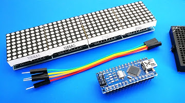
Hi everybody! Today we will examine the "Dot Matrix LED Module" and test it with the example of "Scrolling Text". This LED Matrix “4-in-1” has four singular displays soldered on one piece of a single printed circuit board. You can easily create a "scrolling text" project by getting this module. We needs only five wires and an Arduino Nano (works also with the other Arduino boards). Connect those wires as shown Now we are ready to load the code, but first we need to install the necessary libraries for the display. Open the Arduino IDE, click on “Sketch“, followed by “Include Library”. Click on “Manage Libraries“, a new window will open, the “Library Manager“. In the search-field enter MAX72xx and chose MD_MAX72xx and install it. So, the libraries are installed. Some types of these modules may require a modification. First test the module with an example sketch. As you can see, the letter


Similar products