Description
PWM to voltage module This is a linear conversion module that is output via the internal chip output PWM signal with a voltage signal. Module parameters. 1, the supply voltage: 9V ~ 24V. 2, the signal input voltage range: 4 ~ 24V. 3, the signal input frequency range: 50Hz ~ 10KHz. 4, the signal input duty cycle range: 0 ~ 100%. 5, the output voltage: 0.00V ~ 5.00V / 0.00V ~ 10.00V. 6, the input method: the circuit board S1 pad: the default is open, not used to.. 7, the output mode: S2 pad on the circuit board: open (output 0.00V ~ 5.00V); short (output 0.00V ~ 10.00V), the default is open.. 8, the scope of application: remote data acquisition and control equipment;. 9, size: (long) 26mm * (width) 23mm * (high) 10mm. 10, the module interface:. 24V: Power supply positive interface (9V ~ 24V). G: Power ground interface. IN: Signal input to the positive interface. G: Signal input negative interface. OUT: Signal output interface (0.00V ~ 5.00V / 0.00V ~ 10.00V) G: Power ground interface. Note: When the output 0.00V ~ 10.00V, the power supply voltage to 15 volts power supply. Output (0.00V ~ 5.00V) Resolution: 0.050V / D (V / D)/br> Output (0.00V ~ 10.00V) Resolution: 0.100V / D (V / D)/br> Calculate the measured duty cycle formula: (output voltage (V) / resolution) = duty cycle (%)./br> For example: output (0.00V ~ 5.00V) output is 2.5V/br> (2.5 (V) / 0.05) = 50 (%)./br> package:1pcs PWM to voltage module
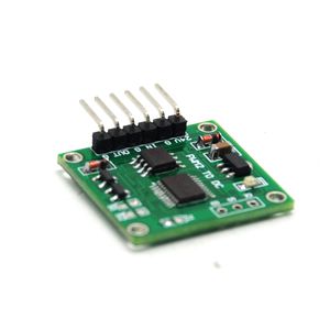
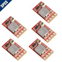
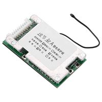
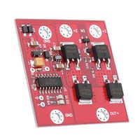
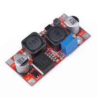
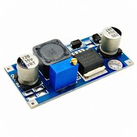
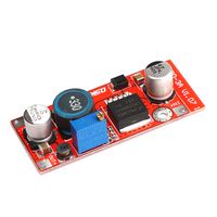
PWM to voltage module 0-100% to 0-5v 0-10v Linear Conversion Transmitter
Current Price
$18.27
Average
$18.27
Min Price
$18.27
Max Price
$18.27
Description
PWM to voltage module This is a linear conversion module that is output via the internal chip output PWM signal with a voltage signal. Module parameters. 1, the supply voltage: 9V ~ 24V. 2, the signal input voltage range: 4 ~ 24V. 3, the signal input frequency range: 50Hz ~ 10KHz. 4, the signal input duty cycle range: 0 ~ 100%. 5, the output voltage: 0.00V ~ 5.00V / 0.00V ~ 10.00V. 6, the input method: the circuit board S1 pad: the default is open, not used to.. 7, the output mode: S2 pad on the circuit board: open (output 0.00V ~ 5.00V); short (output 0.00V ~ 10.00V), the default is open.. 8, the scope of application: remote data acquisition and control equipment;. 9, size: (long) 26mm * (width) 23mm * (high) 10mm. 10, the module interface:. 24V: Power supply positive interface (9V ~ 24V). G: Power ground interface. IN: Signal input to the positive interface. G: Signal input negative interface. OUT: Signal output interface (0.00V ~ 5.00V / 0.00V ~ 10.00V) G: Power ground interface. Note: When the output 0.00V ~ 10.00V, the power supply voltage to 15 volts power supply. Output (0.00V ~ 5.00V) Resolution: 0.050V / D (V / D)/br> Output (0.00V ~ 10.00V) Resolution: 0.100V / D (V / D)/br> Calculate the measured duty cycle formula: (output voltage (V) / resolution) = duty cycle (%)./br> For example: output (0.00V ~ 5.00V) output is 2.5V/br> (2.5 (V) / 0.05) = 50 (%)./br> package:1pcs PWM to voltage module
Price will be lower
in next 2 weeks
in next 2 weeks
According to the data, price will be lower in next two weeks, so not waste your money and track better price!
Product review & video
hi welcome to another video tutorial from Robojax
in this video we are going to do test and review this pulse modulator to voltage converter made
by IC station so their website is IC station comm they send us this product for review and we
are going to do honest review and see how this works in many industrial application or maybe
educational application you need to convert the perfect modulation to the voltage so you want to
find the relationship between the two to maybe control a motor or whatever you want to do so
this module will get a pulse width modulated signal at an input and convert it to the voltage
and will give you the output so the input can be video 0 to 100 percent duty cycle and pulse width
modulation and the output will be between 0 to 10 volts up to 10 volts so this is a module these two
points are for the input which can accept between 12 to


