Description
Description:
1. This is a I2C communication, built-in PWM driver and a clock. This means that this will be very different from the TLC5940 series.
2. You don't need to constantly send signals to occupy your MCU.
3. It's 5V compatible, which means you can also use a 3.3V microcontroller to control and drive safely to 6V output (when you want to control white or blue lights with 3.4 + positive voltage is also possible) 6 address selection pins allow you to hang 62 drive boards on a single I2C bus, with a total of 992 PWM outputs.
4. That will be a huge resource. About 1.6Khz can be FM PWM output for stepper motor output 12 bit resolution.
5. This means that the update rate at 60Hz can reach 4us resolution with configurable push-pull or open-circuit output enabling pins to be quickly disabled.
Feature:
1. The PCA9685 chip is wrapped in the center of the small board.
2. Power input terminal, l green power indicator lamp
3. In four sets of three-pin connectors, it is convenient for you to insert 16 servo motors at a time (the plug of the servo motor is slightly wider than 0.1 ", so you can put 4 pairs of 0.1" connectors) into the reverse polarity protection l cascade design input on the terminal board.
4. Place a large capacitor on the V + line (you will need it in some cases) and the maximum input voltage depends on the capacitance of this 10V1000uf.
5. All PWM output lines have a 220 ohm series resistor to protect them and easily drive LEDs.
Specification:
Model: PCA9685
Size: 68*25*10mm/2.67*0.98*0.39''
Package included:
1 x 16 Channel Module
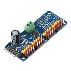
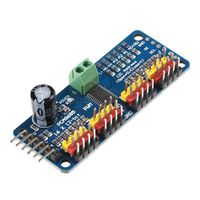
WinnerEco Interface Module PCA9685 16 Channel 12-bit PWM Servo Driver-I2C Interface Module for Arduino
Current Price
$5.9
Average
$5.57
Min Price
$4.9
Max Price
$5.9
Price dynamics
6%
Description
Description:
1. This is a I2C communication, built-in PWM driver and a clock. This means that this will be very different from the TLC5940 series.
2. You don't need to constantly send signals to occupy your MCU.
3. It's 5V compatible, which means you can also use a 3.3V microcontroller to control and drive safely to 6V output (when you want to control white or blue lights with 3.4 + positive voltage is also possible) 6 address selection pins allow you to hang 62 drive boards on a single I2C bus, with a total of 992 PWM outputs.
4. That will be a huge resource. About 1.6Khz can be FM PWM output for stepper motor output 12 bit resolution.
5. This means that the update rate at 60Hz can reach 4us resolution with configurable push-pull or open-circuit output enabling pins to be quickly disabled.
Feature:
1. The PCA9685 chip is wrapped in the center of the small board.
2. Power input terminal, l green power indicator lamp
3. In four sets of three-pin connectors, it is convenient for you to insert 16 servo motors at a time (the plug of the servo motor is slightly wider than 0.1 ", so you can put 4 pairs of 0.1" connectors) into the reverse polarity protection l cascade design input on the terminal board.
4. Place a large capacitor on the V + line (you will need it in some cases) and the maximum input voltage depends on the capacitance of this 10V1000uf.
5. All PWM output lines have a 220 ohm series resistor to protect them and easily drive LEDs.
Specification:
Model: PCA9685
Size: 68*25*10mm/2.67*0.98*0.39''
Package included:
1 x 16 Channel Module
1. This is a I2C communication, built-in PWM driver and a clock. This means that this will be very different from the TLC5940 series.
2. You don't need to constantly send signals to occupy your MCU.
3. It's 5V compatible, which means you can also use a 3.3V microcontroller to control and drive safely to 6V output (when you want to control white or blue lights with 3.4 + positive voltage is also possible) 6 address selection pins allow you to hang 62 drive boards on a single I2C bus, with a total of 992 PWM outputs.
4. That will be a huge resource. About 1.6Khz can be FM PWM output for stepper motor output 12 bit resolution.
5. This means that the update rate at 60Hz can reach 4us resolution with configurable push-pull or open-circuit output enabling pins to be quickly disabled.
Feature:
1. The PCA9685 chip is wrapped in the center of the small board.
2. Power input terminal, l green power indicator lamp
3. In four sets of three-pin connectors, it is convenient for you to insert 16 servo motors at a time (the plug of the servo motor is slightly wider than 0.1 ", so you can put 4 pairs of 0.1" connectors) into the reverse polarity protection l cascade design input on the terminal board.
4. Place a large capacitor on the V + line (you will need it in some cases) and the maximum input voltage depends on the capacitance of this 10V1000uf.
5. All PWM output lines have a 220 ohm series resistor to protect them and easily drive LEDs.
Specification:
Model: PCA9685
Size: 68*25*10mm/2.67*0.98*0.39''
Package included:
1 x 16 Channel Module
Price will be lower
in next 2 weeks
in next 2 weeks
According to the data, price will be lower in next two weeks, so not waste your money and track better price!
Product review & video
My Name is Ahmad Shamshiri and I am presenting this tutorial from Canada. Hi, welcome to Robojax. in this video
I'm going to introduce the PCA9685 servo controller by NXP Semiconductor. This is a 16 channel 12 bit module that can control
or produce pulse width modulation PWM that can be used for servo and also it
can be used for Bank of LEDs to dim it so each of these can be controlled
individually meaning that you can set disc separately a different angle or so
you can see the other one or you can set multiple or all of them
to do the same thing or different thing all the codes, the library the manual and
all the information that you need to run a successful projects for this video is
available at the description or you can directly go to robojax.com/learn/arduino to get all the codes also I'm looking forward to
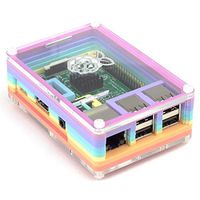
your suggestions and comments. If you have a robot something like this


Similar products
