Description
This is a LOW Level 5V 2-channel relay interface board, and each channel needs a 15-20mA driver current. It can be used to control various appliances and equipment with large current. It is equipped with high-current relays that work under AC250V 10A or DC30V 10A. It has a standard interface that can be controlled directly by microcontroller. This module is optically isolated from high voltage side for safety requirement and also prevent ground loop when interface to microcontroller.
Technical Specifications:
Maximum AC current and voltage : 10A 250VAC
Maximum DC current and voltage : 10A 30VDC
Relay long life can absorb 100000 times in a row
Module with diode current protection, short response time Optocoupler isolation, good anti-interference
Low level pull-in, high-level release. Pull the status indicator light, release the status indicator is off
VCC for the system power, JD_VCC for the relay power. Plug in the jumper cap
PCB Size: 50.5mm x 38.5mm x 18.5mm/1.99″x 1.52″x 0.73″(L×W×H)
NOTE:
1.Some Raspberry-Pi users have found that some relays are reliable and others do not actuate sometimes. It may be necessary to change the value of R1 from 1000 ohms to something like 220 ohms, or supply +5V to the VCC connection.
2.The digital input s from Arduino are Active LOW: The relay actuates and LED lights when the input pin is LOW, and turns off on HIGH.
3. If you want complete optical isolation, connect "Vcc" to Arduino +5 volts but do NOT connect Arduino Ground. Remove the Vcc to JD-Vcc jumper. Connect a separate +5 supply to "JD-Vcc" and board GND.This will supply power to the transistor drivers and relay coils.If relay isolation is enough for your application, connect Arduino +5 and Gnd, and leave Vcc to JD-Vcc jumper in place.
Package inlcuded:
3x 2 Channel 5V Relay Module
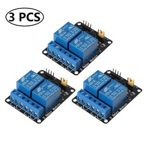
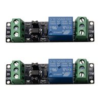
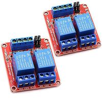
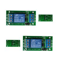
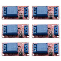
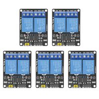
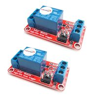
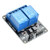
Aokin 3pcs 2 Channel DC 5V Relay Module for Arduino UNO R3 DSP ARM PIC AVR STM32 Raspberry Pi with Optocoupler Low Level Trigger Expansion Board
Current Price
$9.99
Average
$9.49
Min Price
$8.99
Max Price
$9.99
Price dynamics
5%
Description
This is a LOW Level 5V 2-channel relay interface board, and each channel needs a 15-20mA driver current. It can be used to control various appliances and equipment with large current. It is equipped with high-current relays that work under AC250V 10A or DC30V 10A. It has a standard interface that can be controlled directly by microcontroller. This module is optically isolated from high voltage side for safety requirement and also prevent ground loop when interface to microcontroller.
Technical Specifications:
Maximum AC current and voltage : 10A 250VAC
Maximum DC current and voltage : 10A 30VDC
Relay long life can absorb 100000 times in a row
Module with diode current protection, short response time Optocoupler isolation, good anti-interference
Low level pull-in, high-level release. Pull the status indicator light, release the status indicator is off
VCC for the system power, JD_VCC for the relay power. Plug in the jumper cap
PCB Size: 50.5mm x 38.5mm x 18.5mm/1.99″x 1.52″x 0.73″(L×W×H)
NOTE:
1.Some Raspberry-Pi users have found that some relays are reliable and others do not actuate sometimes. It may be necessary to change the value of R1 from 1000 ohms to something like 220 ohms, or supply +5V to the VCC connection.
2.The digital input s from Arduino are Active LOW: The relay actuates and LED lights when the input pin is LOW, and turns off on HIGH.
3. If you want complete optical isolation, connect "Vcc" to Arduino +5 volts but do NOT connect Arduino Ground. Remove the Vcc to JD-Vcc jumper. Connect a separate +5 supply to "JD-Vcc" and board GND.This will supply power to the transistor drivers and relay coils.If relay isolation is enough for your application, connect Arduino +5 and Gnd, and leave Vcc to JD-Vcc jumper in place.
Package inlcuded:
3x 2 Channel 5V Relay Module
Technical Specifications:
Maximum AC current and voltage : 10A 250VAC
Maximum DC current and voltage : 10A 30VDC
Relay long life can absorb 100000 times in a row
Module with diode current protection, short response time Optocoupler isolation, good anti-interference
Low level pull-in, high-level release. Pull the status indicator light, release the status indicator is off
VCC for the system power, JD_VCC for the relay power. Plug in the jumper cap
PCB Size: 50.5mm x 38.5mm x 18.5mm/1.99″x 1.52″x 0.73″(L×W×H)
NOTE:
1.Some Raspberry-Pi users have found that some relays are reliable and others do not actuate sometimes. It may be necessary to change the value of R1 from 1000 ohms to something like 220 ohms, or supply +5V to the VCC connection.
2.The digital input s from Arduino are Active LOW: The relay actuates and LED lights when the input pin is LOW, and turns off on HIGH.
3. If you want complete optical isolation, connect "Vcc" to Arduino +5 volts but do NOT connect Arduino Ground. Remove the Vcc to JD-Vcc jumper. Connect a separate +5 supply to "JD-Vcc" and board GND.This will supply power to the transistor drivers and relay coils.If relay isolation is enough for your application, connect Arduino +5 and Gnd, and leave Vcc to JD-Vcc jumper in place.
Package inlcuded:
3x 2 Channel 5V Relay Module
Price will be lower
in next 2 weeks
in next 2 weeks
According to the data, price will be lower in next two weeks, so not waste your money and track better price!